Signal Generator
SAFETY FIRST: Protective gloves and eyewear are recommended at this point.
To inspect the signal generator see the Ignition System topic.
Removal
Remove the lower fairings. See the Lower Fairings topic for more information.
Remove the upper fairings. See the Upper Fairings topic for more information.
Remove the wire band on the left side of the frame.


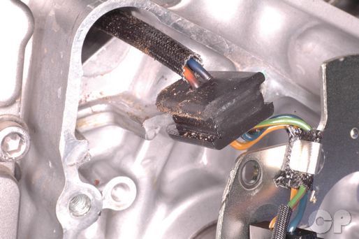
Pull back the rubber wire cover on the right side of the frame.


Unplug the signal generator and the oil pressure switch connectors.


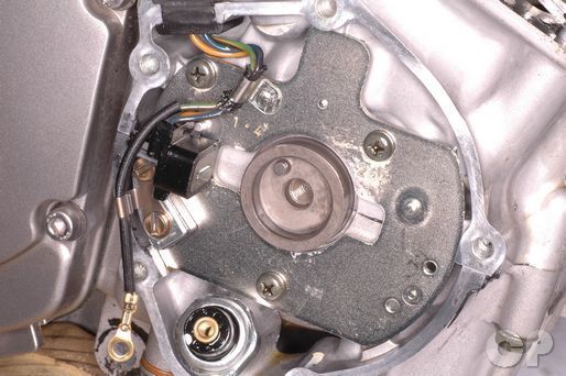
Loosen the five signal generator cover bolts with a 5 mm Allen. Remove the bolts. The forward most bolt has a sealing a sealing washer.
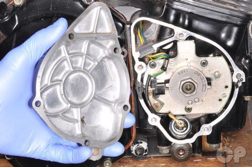
The 1988 - 1995 models have a different looking signal generator rotor from the 1996 and newer models shown below.


Remove the generator cover and gasket.
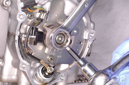
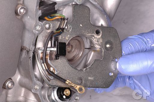
Hold the signal generator rotor with a 19 mm wrench and loosen the bolt with a 6 mm Allen.


Remove the signal generator rotor bolt and rotor.


Remove the oil pressure switch screw with a #2 Phillips screwdriver.


Loosen the three pickup coil bracket screws with a #2 Phillips screwdriver. You may need to use an impact driver to get them loose.


Remove the pickup coil bracket screws.


Free the rubber wire grommet from the engine case. Guide the signal generator and oil pressure switch wires down and out through the crankcase. Remove the pickup coil.


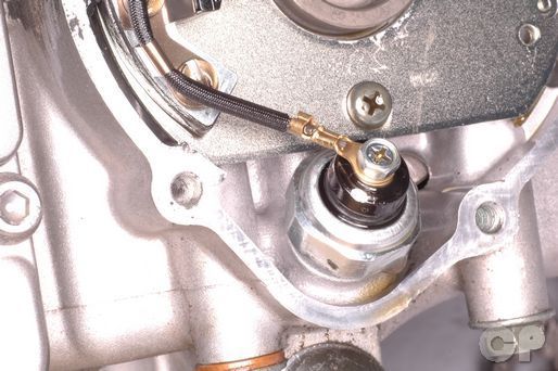
To remove the oil pressure switch loosen it with a 24 mm socket. To inspect the oil pressure switch see the Switches topic.
Installation
Coat the threads of the oil pressure screw in Suzuki Bond or an equivalent sealant. Thread in the oil pressure switch and tighten it to specification with a 24 mm socket.
(Oil Pressure Switch Torque: 14 N-m or 10 lb-ft)
Suzuki Bond: 99104-31140
Guide the signal generator and oil pressure switch wires through the opening in the upper crankcase. Rout the wires through the starter motor mounts.
Coat the rubber wire grommet in Suzuki Bond or an equivalent sealant. Insert the grommet into place in the crankcase.
Suzuki Bond: 99104-31140
Install the pickup coil. Tighten the screws securely with a #2 Phillips screwdriver.
Install the oil pressure switch wire. Tighten the screw securely with a #2 Phillips screwdriver.

Install the signal generator rotor so that the slot in the rotor lines up with the pin on the crankshaft.

Insert the generator rotor bolt. Hold the rotor with a 19 mm wrench and tighten the bolt to specification with a 6 mm Allen.
(Signal Generator Rotor Bolt Torque: 25 N-m or 18 lb-ft)
Plug in the signal generator and the oil pressure switch connectors.
Cover the connectors with the rubber cover.
Install the upper fairings. See the Upper Fairings topic for more information.
Install the lower fairings. See the Lower Fairings topic for more information.
Copyright - Cyclepedia Press LLC

Note: If you are viewing this document offline be sure to visit the latest version online at http://www.cyclepedia.com before attempting any repairs. Updates are made without notice.